Science explained · Technology & Engineering
How Do Undersea Internet Cables Carry the World’s Data?
What must happen between a beach landing station and the moment the same light reaches another continent?
Explore the sections in this article
The route begins long before the beach
When a person in one country requests a page hosted in another, the data does not receive a label saying “take the Atlantic cable.” It travels as packets through networks that exchange reachability information and choose routes according to connectivity, policy, performance and cost. A carrier may hand the packets to another network; a content company may place them on capacity it owns or leases.
Near the coast, terrestrial fibre leads to a cable landing station. The station is more than a shed where a wet cable becomes a dry one. It contains submarine line-terminal equipment, monitoring and control systems, power-feeding equipment, terrestrial interconnection, security and redundancy. Its optical equipment combines traffic into channels suited to the submarine system.
The station also creates an important boundary. The wet plant is everything engineered for the undersea path: cable, repeaters and sometimes branching units. The dry plant on land generates, receives, powers and supervises it. A failure on a terrestrial backhaul link can isolate a perfectly healthy undersea cable; resilient design therefore has to extend inland as well as across the sea.
Information rides on controlled light, not a glowing string of ones and zeros
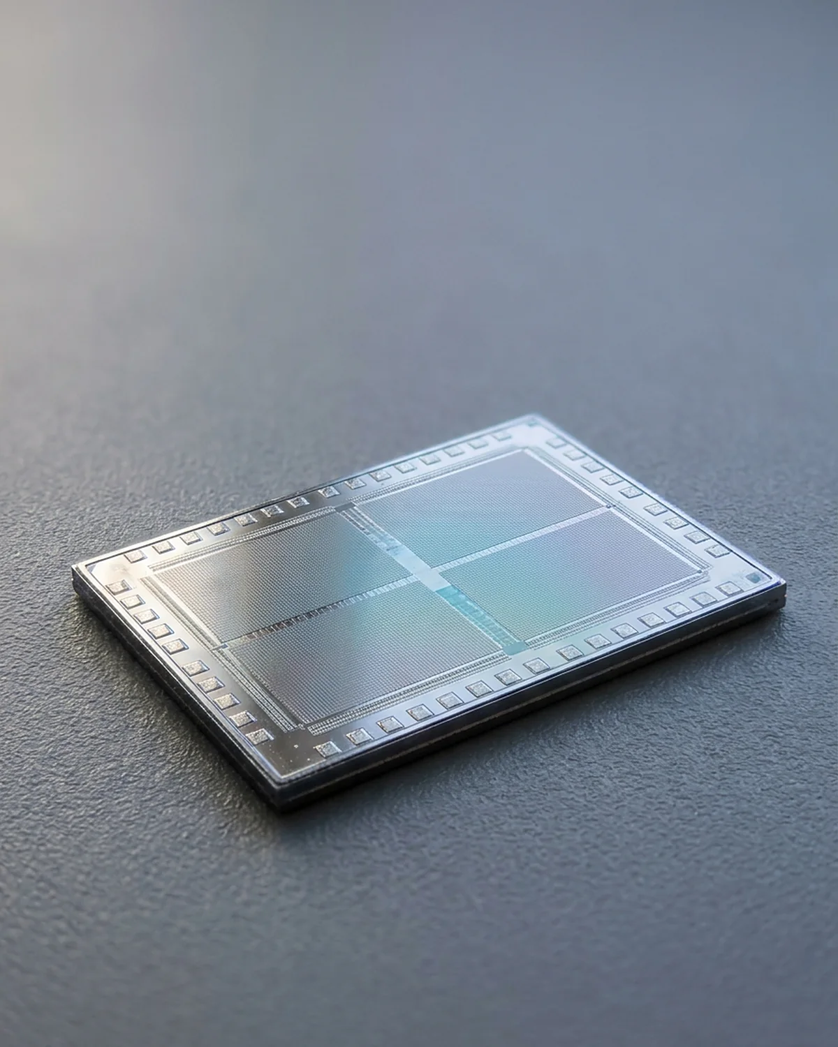
Inside the terminal, lasers produce light at tightly controlled wavelengths. Modulators vary properties of that light so a receiver can recover symbols. Modern systems can encode information using amplitude, phase and polarization and use digital signal processing to correct impairments. The intuitive phrase “light pulses mean ones and zeros” is a useful beginning, but it leaves out how much information can be packed into one optical channel.
Wavelength-division multiplexing places multiple optical carriers—different colours in an engineering sense—on the same fibre. Fibre pairs provide paths in opposite directions. The exact number of fibre pairs, wavelengths, modulation format and capacity belongs to a particular cable design and can change after upgrades; there is no honest universal figure for “how much one cable carries.”
The glass core and surrounding cladding have different refractive-index profiles, forming a waveguide. In a simplified ray picture, total internal reflection confines the light. A more accurate picture treats the field as a guided mode. Either way, the useful point is that light can travel through the fibre with remarkably low loss while remaining sensitive to bending, contamination at a joint, material absorption and scattering.
The data is in the optical field. The thick metal and polymer layers around it are protection and, in repeatered systems, part of the electrical power path. They are not a giant copper Internet wire.
A cable changes as it walks away from shore
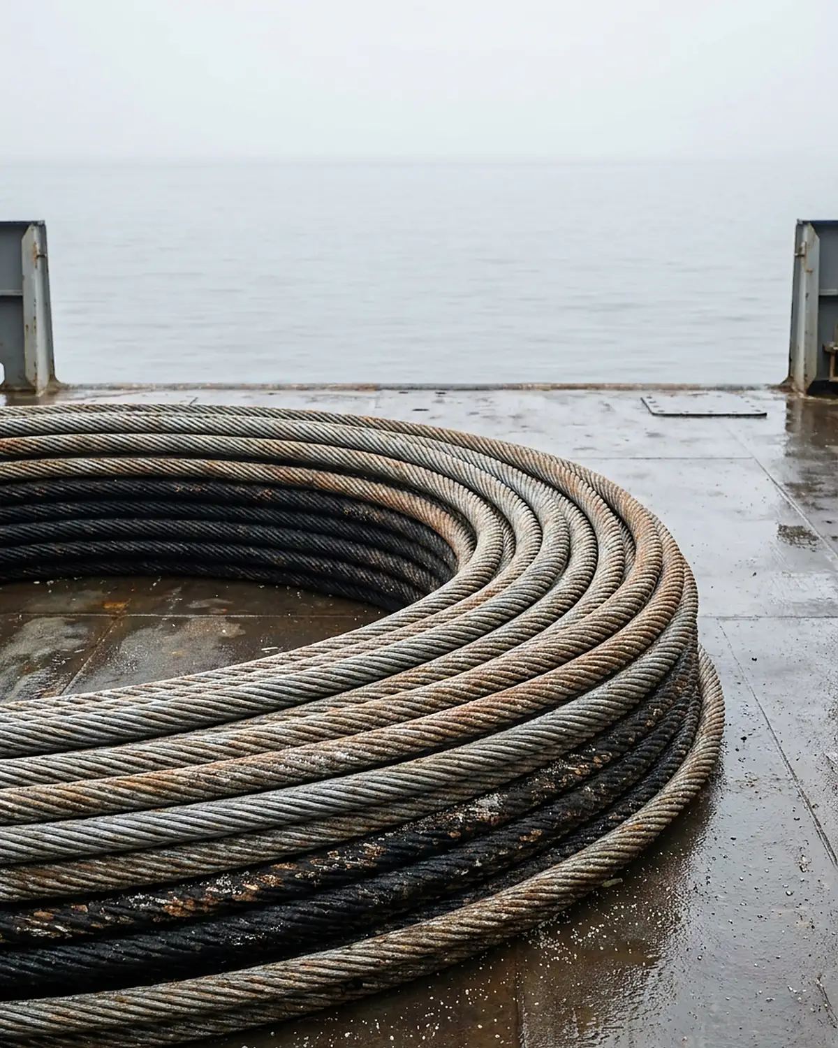
The seabed near a busy coast is hostile. Anchors, trawling gear, dredging, currents and coastal construction can reach a cable. Shore-end sections may therefore be buried where conditions allow and protected with layers of steel-wire armour. A vessel installing the cable may plough or jet a narrow trench and place the cable below the seabed.
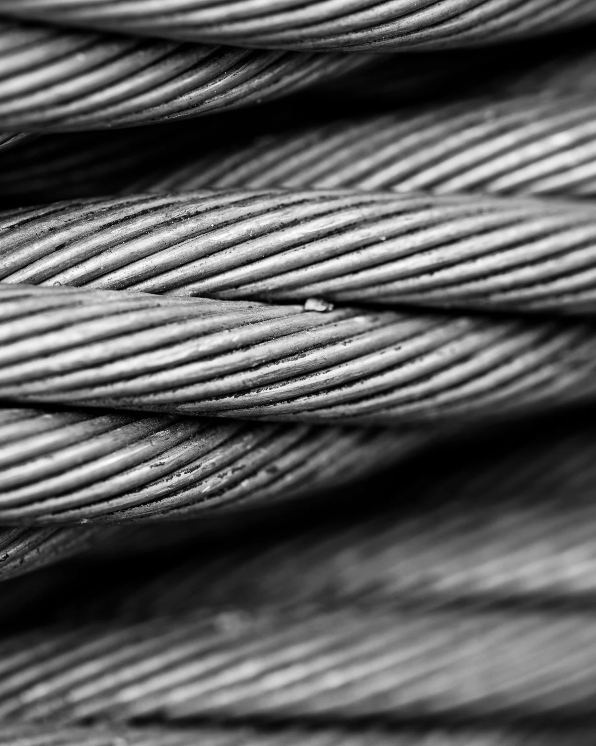
Far offshore, the risk profile changes. Fishing and anchoring generally concentrate in shallower waters, while enormous depth makes installation loads and recovery demanding. Deep-sea cable can use less armour than a shore end, reducing weight. That is why a single photograph of a cut cable does not reveal the construction of every metre on its route.
Route survey comes first. Engineers map slopes, sediment, canyons, known hazards and other seabed uses. They choose a path, plan slack and crossings, obtain permits and coordinate landing works. A straight line on a world map conceals an engineered route that may avoid steep terrain or areas of intense human activity.
International Cable Protection Committee figures illustrate why this care matters. Its 2026 media factsheet says accidental human activity—especially fishing and anchors—accounts for roughly 70–80 percent of submarine telecommunications cable faults in its industry data. Natural hazards and technical failures make up the remainder. That is a global operational summary, not a prediction for every sea. Local depths, shipping patterns, geology and protection practices change the mix.
Repeaters solve fading, not understanding
Even exceptionally clear glass attenuates light. Across thousands of kilometres, a signal launched from one shore would become too weak to recover without help. Repeatered submarine systems place pressure-resistant housings along the route. Inside are optical-amplifier paths that strengthen wavelength bands in both directions.
An erbium-doped fibre amplifier, common in long-haul optical systems, uses pump light to energize erbium ions in a short section of special fibre. Passing signal light stimulates emission at the signal wavelengths. The result is optical gain: the signal becomes stronger without first being translated into ordinary Internet packets.
That distinction matters. A repeater does not read an email, inspect an address and forward a packet. It operates on the optical signal. Amplification also adds noise, and transmission accumulates dispersion and nonlinear effects. System designers budget optical signal-to-noise ratio, power, spacing and margin across the entire line. Coherent receivers and digital processing at the ends help untangle the arriving waveform, but they cannot make physics disappear.
ITU-T Supplement 41 describes repeater housings built for pressure, tension, shock, heat dissipation, recovery and relaying at great depth. It also describes power-feed modules and optical-amplifier pairs. Spacing is a system-design result, not a fixed “one repeater every X kilometres” law. Treat any single interval you see quoted as belonging to one particular cable rather than to cables in general.
Electricity travels alongside the glass
Those amplifiers need continuous power on a route where there are no wall sockets. Power-feeding equipment at landing stations applies high-voltage direct current through a metallic conductor in the cable; the seawater/earth path and system design complete the circuit. Repeaters are connected in series for power while carrying optical channels through fibre.
Long systems may feed from both ends. ITU guidance notes that designs can support double-end feeding and, where engineered, continued single-end feeding after a terminal power-feed failure or certain cable faults. The exact voltage, current and fault response are cable-specific and potentially dangerous; they are not do-it-yourself electrical facts.
The power conductor explains two easily confused observations. First, an undersea cable can carry substantial electrical potential even though the customer data is optical. Second, a cable fault can be optical, electrical or both. Monitoring equipment uses changes in optical and electrical behaviour to help identify what happened and where to investigate.
The ocean imposes a speed limit before any router gets a vote
Latency discussions often blame a service or an indirect route, but some delay is unavoidable. Light travels more slowly in glass than in vacuum—roughly 200,000 kilometres per second is a useful planning approximation. Consider a hypothetical fibre path 6,000 kilometres long:
one-way propagation time ≈ 6,000 km ÷ 200,000 km/s = 0.030 s = 30 ms.
A request and immediate reply would spend about 60 milliseconds on propagation alone if both followed that path. The actual round-trip time would be longer because the physical route is not a perfect geodesic, and because packets encounter terrestrial fibre, optical and electronic equipment, routers, queues, processing and perhaps a different return route.
This calculation is a bound, not a performance promise. It also shows why satellites have different trade-offs. A low-Earth-orbit system can sometimes offer useful paths to remote places; a geostationary satellite adds a much longer space journey. Submarine cable and satellite networks complement one another, but the overwhelming share of international data exchange runs through submarine telecommunications cables. The ITU’s resilience program currently describes that share as over 99 percent.
A break is a geographic event
Network monitoring can detect loss of signal, power changes or degraded channels. Optical time-domain reflectometry sends a test signal and analyses returned scattering and reflections to estimate distance to a fault from a terminal. Cable records and electrical tests add evidence. Translating “distance along the cable” into a position at sea requires the as-laid route and knowledge of cable slack.
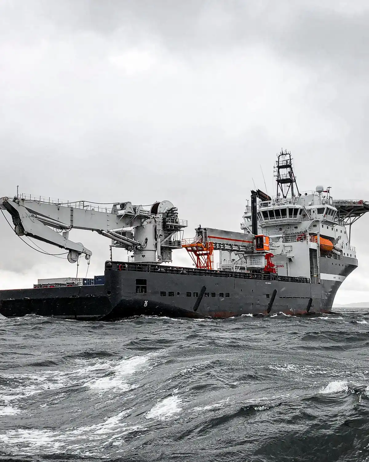
Near shore, land-based or shallow-water work may be possible. In deep water, a repair ship approaches the reported area and uses grapnels or remotely operated equipment suited to the conditions. A common repair sequence is to recover one end, secure it on deck, locate and recover the other end, splice in a new section, test it, and lay the repaired span back with controlled slack. Details vary with depth, weather, burial, cable type and whether a repeater is nearby.
No diver descends several kilometres to twist two ends together. On deck, technicians prepare fibre surfaces with microscopic precision, join fibres with low-loss splices, rebuild mechanical and electrical continuity, protect the joint and verify performance. The ship may have to handle many tonnes of cable tension while keeping a hair-scale optical path clean.
Repair duration is not simply “sailing time.” A suitable vessel must be available, permits and customs processes may be required, weather can close the work window, the fault may be difficult to locate, and multiple simultaneous faults can compete for resources. The 2026 ITU advisory report treats repair architecture and regulatory coordination as parts of resilience for exactly this reason.
Redundancy is a map, not a duplicate disk
If one cable fails, Internet routing can steer traffic toward other paths. That familiar sentence hides three conditions: another path must exist, it must be operationally reachable, and it must have enough usable capacity. A country connected through several cables that share one landing area, one terrestrial corridor or one geological hazard may have less diversity than the line count suggests.
True route diversity asks uncomfortable questions. Do the cables land far enough apart? Do they cross the same narrow sea passage? Do their inland links enter the same building? Are repair ships and spares available in the region? Can operators exchange traffic during an emergency? Is there enough spare capacity when normal demand is shifted?
Rerouting can keep applications alive while increasing latency or congestion. Some sessions may reset. A small island with only one or two practical paths can experience severe disruption, while a dense hub may absorb a single break quietly. The cable itself can be highly reliable and the service still fragile because resilience is a property of the network around it.
The human system is as important as the optical one
Submarine cables are a rare technology whose operation depends on agreements across engineering cultures and national borders. Surveyors negotiate marine space with fishers and ports. Governments license landings. Hydrographic offices chart routes. Network operators share fault information. Maintenance zones retain specialist vessels. Crews practice grappling and jointing skills that are needed unpredictably but cannot be improvised after a break.
The first transatlantic telegraph cables of the nineteenth century exposed many of the same categories of difficulty: insulation, attenuation, laying tension, fault location, repair and the temptation to push a system beyond what measurement supported. Modern coherent optics would be unimaginable to those crews, but the ocean still punishes optimistic assumptions.
Before a modern system carries customer traffic, specialists create a baseline that future operators will depend on. During manufacture and installation they test fibre attenuation, splice loss, insulation and conductor continuity. After the final landing, they measure end-to-end optical performance, amplifier behaviour, power-feed stability and channel margins. The as-laid position is recorded because a planned route and the cable that settled onto the seabed are not identical lines.
Commissioning is where a map becomes an operating instrument. A future loss increase can be compared with baseline traces. A power anomaly can be interpreted against known electrical values. A repair joint can be accepted only after tests show that the recovered route still meets its system budget. The record is as important as the measurement: a distance-to-fault result without accurate cable length and route data points to the wrong patch of ocean.
Capacity upgrades add another human chapter. Terminal equipment can sometimes be replaced with more capable modulation and digital processing while the wet plant remains in place. Engineers call this a terminal upgrade, but it is not unlimited. Older fibre, repeater bandwidth, optical noise and nonlinear limits define how much new terminal intelligence can recover. The cable may outlive several generations of equipment precisely because the original designers reserved margin rather than claiming every theoretical bit on day one.
The most accurate mental model is therefore not “the cloud under the sea.” It is a chain of measured conversions and maintained places. Packets become a modulated optical field. The field crosses engineered glass. Amplifiers use shore-fed electricity to preserve it. Terminals recover symbols. Routers choose what happens next. Ships and people make the route repairable.
An ocean cable succeeds not because it escapes geography, but because its designers take geography seriously.
Explore the idea
Try it: the delay distance cannot avoid
Choose a fibre route length. Estimate the travel time of a signal before routers, queues, processing and the rest of the route add their delays.
Time = distance ÷ speed. This example assumes a propagation speed of 200,000 km/s in fibre.
This is an approximate propagation-only calculation, not a ping forecast or a measurement of a particular cable. Real routes are longer than straight-line map distances.
Model background: ITU-T G.114: one-way transmission time
Frequently asked questions
Are undersea Internet cables thicker than a garden hose?
Some deep-sea cable sections are often compared with a garden hose, but construction varies along a route. Shore ends may have heavy steel armour and burial protection; deep-water sections can be slimmer. The useful comparison is the layered structure, not one universal diameter.
Do sharks cause most cable failures?
No. Shark bites have occurred, but current ICPC industry figures identify accidental human activity—especially fishing and ship anchors—as the dominant global category. Natural hazards and technical causes also matter. The cause distribution differs by region.
Why not send all international traffic through satellites?
Satellites are valuable for mobility, broadcasting, resilience and places difficult to reach by cable. But fibre offers enormous capacity and, on many major routes, lower propagation delay and cost per transmitted bit. The systems serve overlapping but different needs.
Can a repeater read the data passing through it?
A traditional optical repeater/amplifier in the wet plant strengthens optical channels; it does not operate like an Internet router interpreting packet addresses. Security still depends on end systems, network equipment and encryption—not on assuming a physical link is inaccessible.
How deep are the cables buried?
Burial is mainly used in selected shallow-water and shore approaches where seabed conditions and risk justify it. In deep ocean, cable is commonly laid on the seabed. Burial depth and method are route-specific, so there is no global answer.
Does one cut disconnect a whole country?
It can cause anything from an invisible reroute to a major outage. The outcome depends on independent alternative paths, landing and terrestrial diversity, available capacity, operator arrangements and the services involved.
How can technicians find a fault beneath thousands of kilometres of water?
Terminal tests estimate distance along the fibre or electrical conductor to the discontinuity. Operators combine that result with the cable’s as-laid route, monitoring history and marine information, then a repair vessel searches the target area.
Is the cable dangerous to marine life?
Telecommunications cables have a small physical footprint compared with many marine structures, but installation, burial, repair and abandonment still require environmental assessment and careful route planning. Effects depend on habitat, method and local conditions; “no impact” would be too broad.
Sources & further reading
This explainer was prepared through desk research using the sources below; established findings are distinguished from open questions in the text. See our editorial methodology.
- International Telecommunication Union, “Submarine Cable Resilience.”
- ITU-T G.971 (12/2024), “General features of optical fibre submarine cable systems.”
- ITU-T G Supplement 41 (07/2024), “Design guidelines for optical fibre submarine cable systems.”
- International Advisory Body on Submarine Cable Resilience, 2026 Working Group Reports.
- International Cable Protection Committee, “Media Enquiries & Frequently Asked Questions” (2026).
- ICPC, “Damage to Submarine Cables from Dragged Anchors” (2025).
- Federal Communications Commission, “Submarine Cable Landing Licenses.”
- Corning Optical Communications, “Optical Fiber Glossary of Terms.”
- International Telecommunication Union, “Overview of ITU’s History.”
Spotted an error? We correct verified mistakes promptly — email contact@flashscience.org.
11 September 2026 update: added a sourced interactive model and clarified its assumptions. Editorial change log
Continue exploring