Science explained · Technology & Engineering
How Does Camera Autofocus Find a Sharp Image?
How can a camera know which way to move a lens before the picture is sharp?
Explore the sections in this article
A lens maps object distance to image distance
A simple thin lens follows:
1/f = 1/u + 1/v,
where f is focal length, u is object distance and v is image distance. For a 50 mm thin lens focused on an object 1,000 mm away:
1/v = 1/50 − 1/1000 = 0.019 mm⁻¹, so v ≈ 52.63 mm.
For an object effectively at infinity, v approaches 50 mm. The idealized image-plane difference is therefore about 2.63 mm. That is large compared with a pixel but small enough that precise mechanics matter.
A real photographic lens is not one thin element. It contains multiple groups, and internal focusing may move only some elements, changing focal length and aberrations slightly. The calculation provides scale, not a prescription for moving a specific product’s lens by 2.63 mm.
When the sensor lies at the image plane for one subject distance, points at other distances form blur circles. Aperture, focal length, focus distance, sensor sampling and acceptable viewing conditions determine how much blur still appears “sharp.” Focus is not a binary property of the whole three-dimensional scene.
Contrast detection climbs a hill
A sharply focused edge changes rapidly from dark to light across nearby pixels. Defocus spreads that transition, reducing high-spatial-frequency contrast. A camera can calculate a focus measure from local differences, gradient energy or frequency content in a selected region.
Move the focus group through positions and the metric often rises toward a maximum, then falls. Contrast-detection autofocus searches for that peak. It measures the final image on the imaging sensor, so it can be highly accurate for the chosen metric and aperture.
But one measurement on the slope does not automatically say which direction leads uphill. The camera may move slightly, remeasure and reverse if the score worsens. That trial produces the familiar “hunting” in dim or low-texture scenes.
A simple illustrative metric is the sum of squared differences between neighboring pixel values. For one row [20, 25, 80, 85], differences are 5, 55 and 5; squares total 25 + 3025 + 25 = 3075. A blurred row [35, 45, 60, 70] gives differences 10, 15 and 10; squares total 100 + 225 + 100 = 425. Under this toy metric, the sharper edge scores higher. Noise can also raise differences, so real systems filter, select frequencies and integrate evidence.
Phase detection can reveal direction
Imagine covering the left half of a lens, then the right half. When the image plane is correctly placed, the two sub-aperture views align. When defocused, they are displaced relative to one another. The sign of the displacement reveals whether focus lies in front of or behind the sensor; its magnitude relates to the correction.
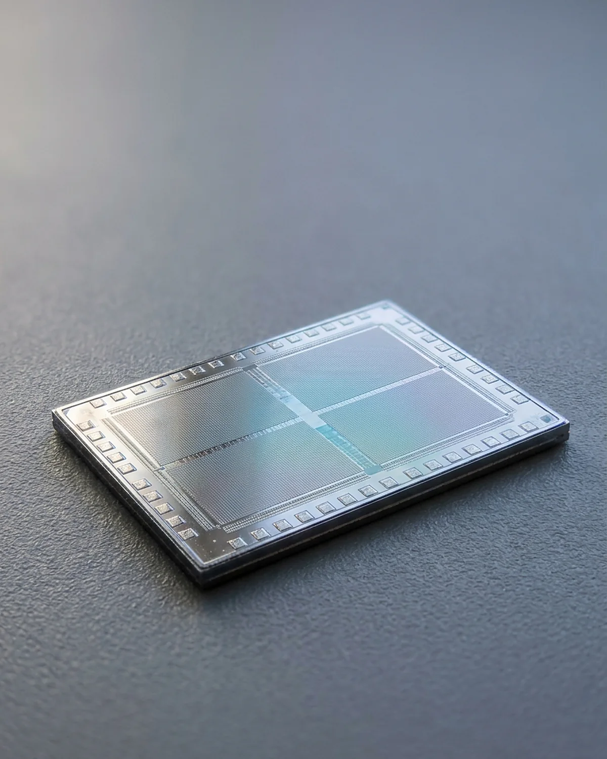
Dedicated phase-detection autofocus in many interchangeable-lens cameras diverts some light to a separate sensor. On-sensor phase detection uses selected or split photodiodes in the image sensor to compare sub-aperture light. Dual-pixel designs divide each pixel’s light-sensitive area into paired photodiodes for phase information, then combine signals for imaging.
The camera correlates patterns in the paired views, estimates phase difference and commands a lens movement. Calibration maps measured disparity to focus-group position. It then verifies because lens backlash, subject movement, temperature and optical tolerances prevent a perfect one-step guarantee.
Phase detection’s directional clue is why it can snap decisively toward focus. It still needs texture visible in both sub-aperture signals. Repeating patterns can create ambiguous matches; very small effective apertures reduce the usable baseline; low light raises noise.
“Phase” here is not usually the optical wave’s raw phase
The term can mislead. Conventional photographic phase-detection autofocus compares the relative position or phase of intensity patterns formed from different portions of the aperture. It is not generally measuring the electromagnetic carrier phase of visible light, whose frequency is hundreds of terahertz.
This distinction matters for diagrams. Two separated ray bundles and shifted images are appropriate. Drawing a camera directly counting visible-wave crests would describe a different interferometric measurement.
The motor is part of the measurement
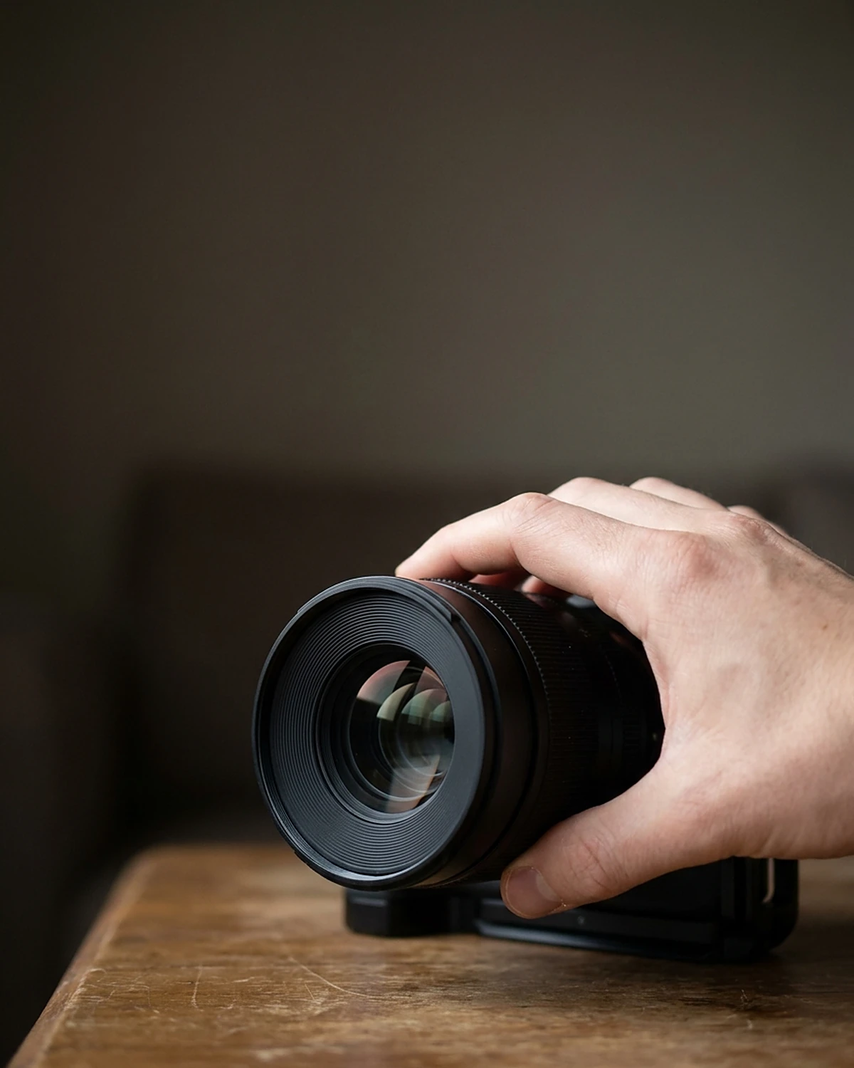
Once the camera estimates correction, an actuator moves a lens group. Lens systems use technologies such as ultrasonic motors, stepping motors, voice-coil or linear electromagnetic drives. Gears, helicoids and guides translate motion while encoders or drive models report position.
The fastest algorithm cannot overcome a heavy focusing group, mechanical play or a slow communication protocol. Conversely, a fast motor can overshoot without good control. Manufacturers balance speed, noise, precision, size, power and video smoothness.
Some lenses focus by moving internal lightweight groups. “Focus breathing”—a change in framing as focus changes—arises because effective focal length and magnification shift. Cinema and high-end designs may reduce it; software may compensate in compatible systems.
Subject detection answers a different question
Modern cameras can detect faces, eyes, animals, vehicles or other patterns. This does not replace the optical focus measurement. Subject detection chooses where in the frame to evaluate or track. Phase or contrast information estimates how the lens must move to focus that region.
A face box can be correct while focus lands on eyelashes instead of iris, or on a foreground branch crossing the box. Detection models have uncertainty and can fail with occlusion, lighting, unusual appearance or domain shift. The label “eye AF” describes a coordinated system, not a sensor that directly understands a person’s gaze.
Face and eye detection also raise privacy questions when images are stored, transmitted or linked to identity. Local ephemeral detection for focus is not automatically face recognition. Product documentation should state what data leaves the device and what is retained.
Continuous autofocus predicts the future
For a stationary subject, the loop can converge and stop. A moving subject changes distance during focus acquisition and shutter delay. Continuous autofocus estimates motion from successive measurements and predicts where the subject will be when the exposure occurs.
Suppose measured subject distances are 8.0 m, 7.5 m and 7.0 m at intervals of 0.1 s. A simple radial estimate is an approach of 0.5 m per 0.1 s = 5 m/s. If capture is expected 0.06 s later, constant-velocity extrapolation predicts another 0.30 m closer, near 6.7 m. Real trackers combine noisy measurements, lens dynamics and nonconstant motion; the arithmetic illustrates why focus must lead rather than follow.
Burst cameras may use subject location, size, optical flow and inertial data to maintain a track. If the subject turns, accelerates or disappears, prediction uncertainty grows. A professional system should be judged by hit rate under specified motion and light, not one best-case acquisition number.
Light level changes signal quality
In darkness, fewer photons reach the autofocus measurement. Photon arrival has statistical variation called shot noise; sensor and electronics add read noise. The phase correlation or contrast metric becomes less certain.
A wider aperture admits more light and creates a wider phase-detection baseline, but the autofocus system may view through an aperture determined by lens and camera design rather than the taking aperture selected for exposure. Some cameras temporarily use an assist lamp; others use near-infrared projection or a flash unit’s pattern. Compatibility and eye-safety rules are product-specific.
Low contrast can be as troublesome as low light. A bright blank wall provides many photons but few edges. A striped fabric offers structure, though a phase sensor whose line orientation matches the stripes poorly may struggle. Cross-type AF points analyze more than one orientation.
Aperture changes both measurement and tolerance
A large aperture creates shallow depth of field, so small focus errors become visible. It also supplies a broad cone of rays that can improve phase sensitivity. Stopping down increases depth of field but reduces light and can introduce diffraction softness at very small apertures.
Many cameras focus with the lens relatively open, then stop down for exposure. Residual optical effects can shift the best focus slightly between apertures in some lens designs. Mirror-based phase systems can also suffer calibration mismatch between the separate AF path and imaging sensor, producing systematic front- or back-focus. On-sensor measurement avoids that particular path mismatch, though it has other design trade-offs.
Depth of field is not a physical slab where everything is equally sharp. Only one object plane is exactly conjugate to the sensor for the simplified lens. Acceptable sharpness expands around it according to blur tolerance, output size and viewing distance.
Why autofocus hunts or chooses the wrong thing
Hunting can result from weak contrast, low light, a subject outside the lens range, transparent surfaces, repetitive texture or a moving target. A camera may lock confidently on the wrong plane because that plane provides stronger structure. A fence, window reflection or foreground leaf is not a measurement failure if the selected focus area includes it; it is a target-selection failure.
Heat shimmer and atmospheric turbulence make distant details fluctuate. Flickering light changes measurements between samples. Video autofocus may intentionally move slowly to avoid visible jumps. Still-photo settings optimized for speed can look abrupt in a movie.
No single AF mode wins every scene. Single-shot modes suit stationary subjects. Continuous modes suit motion. Zone selection tolerates framing change but risks foreground capture. A small point gives control but requires accurate placement. Manual focus with magnification or focus peaking is valuable for macro, astronomy and repeatable studio work.

How engineers test autofocus
An honest test needs more than photographing a slanted ruler once. Researchers and manufacturers use targets with controlled texture and illumination, known distances, repeated runs and objective sharpness measures. They separate acquisition time from accuracy and test motion, low light, different lens apertures and positions in the frame.
A 90% hit rate from ten frames means nine successes, but the sample is tiny. From 1,000 randomized trials across specified conditions, 900 successes support a much narrower estimate—yet only for those conditions and the chosen success threshold. Firmware and lens combinations can change results.
The International Organization for Standardization publishes photography standards, while CIPA and manufacturers define additional test conventions. When comparing marketing numbers, check target contrast, illumination, lens, AF area, start position and whether an assist light was used.
A safe observation: give the camera and then remove information
Set a camera or phone on a stable surface. In good light, focus alternately on a printed book cover and a blank wall at the same distance. Use the same focus area and do not point any AF assist emitter into eyes. The textured cover should give the system more spatial information; the wall may slow, hunt or retain the previous distance.
Next place a foreground object near the edge of a broad AF zone. Observe whether the system selects it instead of the intended subject. Switching to a smaller selectable point tests target choice, not optical power. Record only your own objects or consenting participants, and delete test images if they are unnecessary.
Sharpness is an agreement among optics, measurement and intent
Autofocus turns blur into a control signal. Contrast detection asks which position maximizes image structure. Phase detection asks how two sub-aperture views are displaced. A motor changes lens geometry. Tracking extrapolates motion. Subject detection decides which evidence to privilege.
None of these systems knows the artistic subject with certainty. A photographer may want the reflection rather than the face, the bird rather than the branch, or deliberate defocus. The machine solves a measurable proxy under a selected area and mode.
That boundary is not a disappointment. It is the reason autofocus can be understood and improved. Sharpness appears effortless only because optics, sensors, mechanics and prediction complete their loop before the shutter’s click.
Focus and resolution are not the same variable
A perfectly focused image can still lack fine detail because of lens aberrations, diffraction, motion blur, atmospheric turbulence, sensor sampling or aggressive noise reduction. Conversely, sharpening software can increase edge contrast in a slightly defocused image without recovering all lost spatial information. Autofocus chooses a lens position; it does not certify total image quality.
Engineers describe optical performance with the modulation transfer function, which reports how contrast survives at different spatial frequencies. Focus shifts the MTF response, but a single autofocus metric usually samples selected regions and frequencies rather than reconstructing the full function. ISO 12233 test charts and slanted-edge methods help measure camera-system spatial frequency response under controlled conditions.
This also explains why the “maximum contrast” position can vary with color and image location. Lenses have chromatic and field-dependent aberrations; a focus point near the frame edge may not share the center’s best plane. Cameras and lenses use calibration tables and correction models, but no focus setting makes every wavelength and field point ideal.
Range sensors can help without replacing image focus
Some phones and cameras add time-of-flight, lidar-like or stereoscopic depth estimates. A range measurement can give an initial lens command, reducing search, especially where image texture is weak. Yet a depth sensor has its own resolution, reflectivity, interference and calibration limits. Its measured point may not coincide exactly with the imaging pixel chosen for focus.
Hybrid control treats range as another clue. The final image sensor can verify whether the intended region is sharp, while inertial sensors and subject tracking estimate change. Combining independent signals improves robustness only if the system knows when each is unreliable.
The broader principle extends beyond cameras: measurement systems rarely “see” the desired quantity directly. They infer it from signals, calibrations and models, then close a feedback loop. Autofocus feels instantaneous because that loop hides its uncertainty well—not because uncertainty vanished.
Explore the idea
Try it: how far does the image plane move?
Keep a simple lens at 50 mm focal length and move the subject. Compare the image distance with the 50 mm position for a very distant subject.
Image distance v = f × u ÷ (u − f), with all distances in millimetres.
A thin-lens model illustrates the scale of the change. Real lenses move internal groups and can change effective focal length; this is not an adjustment instruction for a camera.
Model background: NIST: imaging optics and camera characterization
Frequently asked questions
What is the difference between phase-detection and contrast-detection autofocus?
Contrast detection searches for a lens position that maximizes a sharpness metric. Phase detection compares sub-aperture images to estimate direction and defocus. Many cameras combine them.
Why does autofocus fail on a blank wall?
A uniform surface has little spatial structure to compare. The camera may receive plenty of light but lack edges needed for a reliable contrast or phase match.
Does autofocus use a laser?
Usually phase and contrast AF use image-forming light. Some devices add an infrared or structured-light assist, and some rangefinding modules use time-of-flight. The technology and eye-safety class are product-specific.
Why are eyes sharp but the nose blurry?
At close distance and wide aperture, depth of field can be very shallow. The eye and nose lie at different distances, so only one may fall within the chosen blur tolerance.
Is manual focus more accurate?
It can be better when the intended plane is ambiguous, the scene is static or magnified live view provides precise feedback. Autofocus is often faster and more repeatable for motion. Accuracy depends on method and conditions.
What is back-button focus?
It assigns autofocus activation to a separate rear control rather than the shutter button. This lets a photographer choose when to update focus independently of taking the picture; it does not change optical focus physics.
Why does my lens “breathe” while focusing?
Internal lens-group motion can change effective focal length and magnification, altering framing. Video-oriented lenses and compatible software may reduce or compensate for the effect.
Does eye autofocus identify who a person is?
Not necessarily. Detecting an eye region for focus is a different task from matching a face to an identity database. Product implementations vary, so check whether images or biometric templates are stored or transmitted.
Sources & further reading
This explainer was prepared through desk research using the sources below; established findings are distinguished from open questions in the text. See our editorial methodology.
- Krotkov, “Focusing,” International Journal of Computer Vision 1, 223–237 (1988) — focus measures, search and computational focusing foundations.
- Canon Inc., “Canon develops new Dual Pixel CMOS AF technology” (2013) — manufacturer technical description of dedicated and image-plane phase-difference AF, split photodiodes, direction/amount estimation and contrast-AF peak search; historical product source, not a universal current architecture.
- OpenCV, Laplacian Operator tutorial — second-derivative edge detection, relevant to illustrating high-frequency/edge-based focus metrics, not a claim that cameras use this exact implementation.
- ISO, ISO 12233:2024 Photography — Electronic still picture imaging — Resolution and spatial frequency responses — current standardized image-resolution measurement context.
- Fox, Kornegay & Silver, NIST, “Imaging Optics and CCD Camera Characterization for Metrology” (2017) — calibrated camera/lens spatial-frequency variation and imaging-metrology context.
- NIST, Privacy Framework Version 1.0 — privacy risk management for image processing, storage and linked identity.
- International Electrotechnical Commission, IEC 62471 Photobiological safety of lamps and lamp systems — safety framework relevant when any autofocus-assist emitter is discussed; use current adopted edition for product claims.
- Chan & Chen, “Improving the Reliability of Phase Detection Autofocus,” Electronic Imaging (2018) — on-sensor phase-detection pixels, amount/direction of lens offset and noise/contrast/calibration limitations.
Spotted an error? We correct verified mistakes promptly — email contact@flashscience.org.
11 September 2026 update: added a sourced interactive model and clarified its assumptions. Editorial change log
Continue exploring